MSO/DS4000 Series is the new mainstream digital scope to meet the customer’s applications with its innovative technology, industry leading specifications, powerful trigger functions and broad analysis capabilities.
Mix Signal Oscilloscope
Models
BW
Max. Sample rate
Max. Memory Depth
Max. Waveform Capture rate
Channels
DS4054
500MHz
4GSa/s
140Mpts
110,000 wfms/s
4
Feature and Benefits:
Bandwidth 500MHz, 350MHz,200MHz,100MHz
Sample Rate Analog channel up to 4 GSa/s, Digital Channel up to 1 GSa/s(MSO)
Standard Memory depth: Analog channel up to 140 Mpts, Digital Channel up to 28 Mpts(MSO)
2 or 4 Analog Channels, 16 Digital channels(MSO)
Waveform capture rate Up to 110,000 waveforms per second,
Real Time Waveform Record, Replay & Analysis(Std. up to 200,000 frames)
Lower noise floor, the Min. vertical sensitivity is 1mV/div
Innovative “UltraVision” technology
A variety of Trigger functions
Support serial bus trigger(Std.) and decoding(Opt.) for both analog and digital channels
Complete Connectivity: USB Host& Device, LAN(LXI-C), VGA, AUX,USB-GPIB(Opt.)
9 inch WVGA(800X480), 256 level intensity grading display
Advanced functions
Large screen display , novel and beautiful appearance
UltraVision: Up to 110K Waveforms/s Waveform capture rate
UltraVision: Realtime waveform record,replay, analysis function (std.)
UltraVision: Deeper Memory with Multi-Level intensity grading display
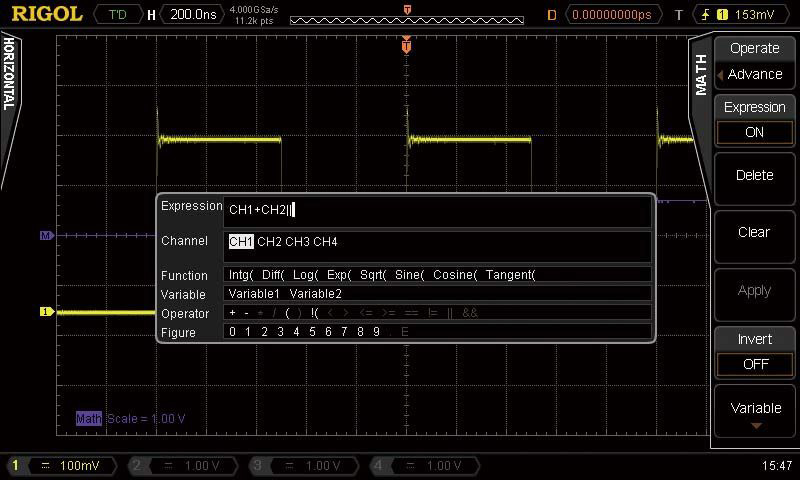
Advanced math function (user defined)
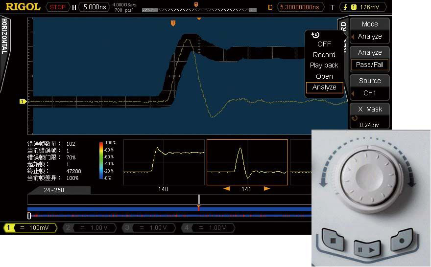
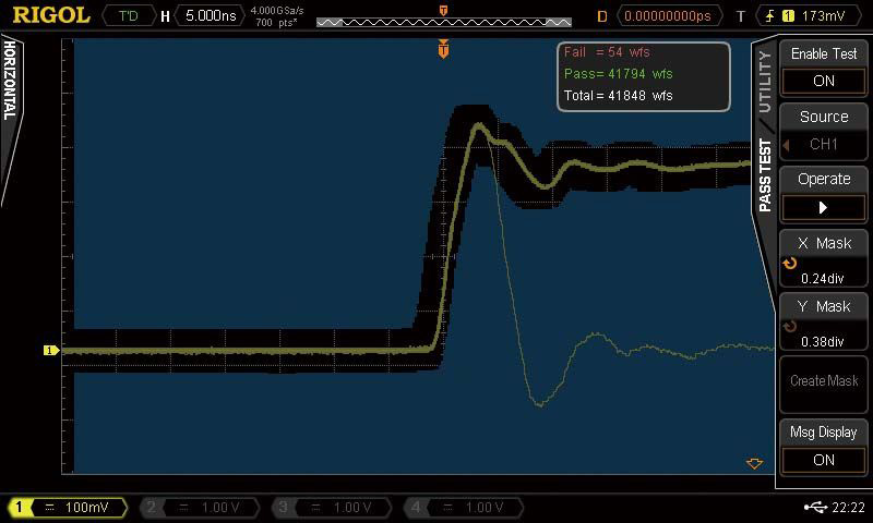
Mask test functions
Automatic measurements with statistics
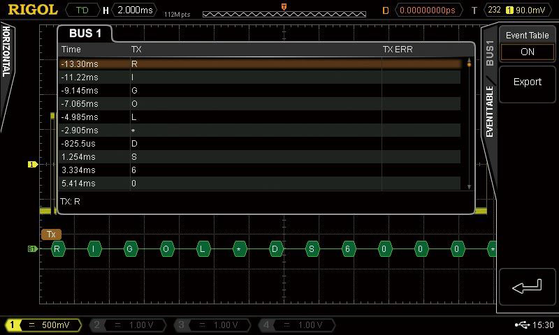
Serial bus Triggering and Decoding (Support both Analog and Digital channels)
Serial bus decoding functions : RS232/UART
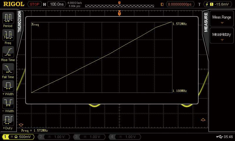
Measurement History: Show the trend of the parameters
Mixed Signal Analysis with analog and digital channels
Easy to be grouped and labeled for digital channels
Serial bus triggering and decoding on digital channels
After all the channels finish N samples at the same time, N can be 2, 4, 8, 16, 32, 64, 128, 256, 512, 1024, 2048, 4096 or 8192.
High Resolution
12 bit of resolution When ≥5 μs/div @ 4 GSa/s (or ≥10 μs/div @ 2 GSa/s).
Memory Depth
Analog channel:Single-channel: Auto, 14k pts, 140k pts, 1.4M pts, 14M pts and 140M pts are availableDual-channel: Auto, 7k pts, 70k pts, 700k pts, 7M pts and 70M pts are available


MSO4054 500MHZ 4CH Mixed Signal Oscilloscope
Call For Price
Product Description
MSO/DS4000 Series is the new mainstream digital scope to meet the customer’s applications with its innovative technology, industry leading specifications, powerful trigger functions and broad analysis capabilities.
Mix Signal Oscilloscope
Feature and Benefits:
Advanced functions
Large screen display , novel and beautiful appearance

UltraVision: Up to 110K Waveforms/s Waveform capture rate
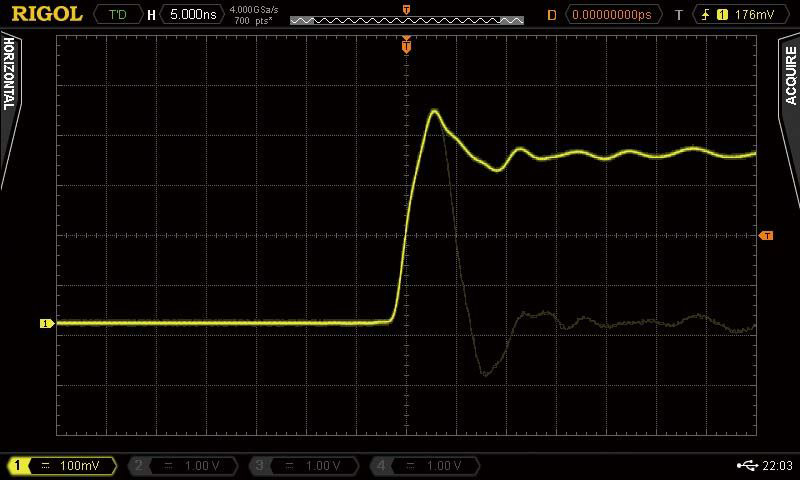
UltraVision: Realtime waveform record,replay, analysis function (std.)
UltraVision: Deeper Memory with Multi-Level intensity grading display

Advanced math function (user defined)
Mask test functions
Automatic measurements with statistics

Serial bus Triggering and Decoding (Support both Analog and Digital channels)

Serial bus decoding functions : RS232/UART
Measurement History: Show the trend of the parameters
Mixed Signal Analysis with analog and digital channels

Easy to be grouped and labeled for digital channels

Serial bus triggering and decoding on digital channels

Support a variety of logic levels

Complete Connectivity

Specification:
Digital channel: maximum 28 M pts
DS40x2: dual-channel
With RP3300 10:1 probe: CAT II 300 Vrms
With RP3500 10:1 probe: CAT II 300 Vrms
With RP5600 10:1 probe: CAT II 300 Vrms
Digital channel: CAT I 40Vrms, transient overvoltage 800 Vpk
MSO401X/DS401X: 5 ns/div to 1000 s/div
MSO401X/DS401X: DC to 100 MHz
MSO401X/DS401X: DC to 100 MHz
230 mV/div to 5 V/div: ± 40 V (1M Ω)
MSO401X/DS401X: 3.5 ns
ECL (-1.3 V)
PECL (+3.7 V)
LVDS (+1.2 V)
0 V
User
Share this: